Because this project is nearly finished and fully working for more than one year now, we will begin by the electronic parts.
For this project i used this electronic components :
- NodeMcu V3 CH340G CH340 ESP8266 ESP-12E Sans Fil WIFI -> Find it
- 1602-LCD Screen, 16×2, PCF8574T, PCF8574 1602, with IIC interface, I2C, 5V -> Find it
- 4 push buttons -> Find it
- 2 linear actuators (Size depends of your solar tracker conception) -> Find it
- 1 ADS1115 (Optional, only needed for future Solar Sensor mode – Not needed for Solar Position) -> Find it
- 1 MCP23017 board -> Find it
- 1 GY521 / MPU6050 -> Find it
- 1 L298 H-Bridge -> Find it
- 1 DC plug -> Find it
- Prototype boards -> Find it
- Anemometer actualy used -> Find it
- Anemometer (better one to be connected to A0 for instant measuring – not implemented yet) -> Find it
- Dupont câbles -> Find it
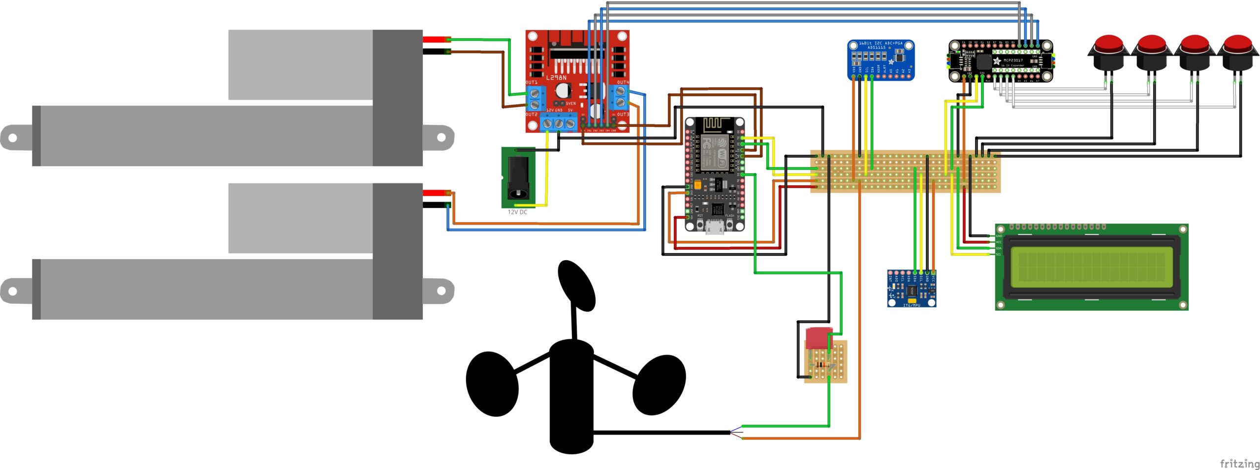
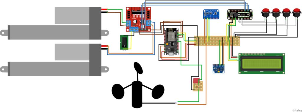
Here is the full wiring diagram of the actual version :


Leave a Reply